Trigger-body reference
Identify the physical feature used to distinguish the required rotational direction and confirm that it is consistent across production components.

Feeding and orientation
Trigger spray closures are oriented by identifying repeatable features of the trigger body and controlling how each closure moves through the feeder and hand-off. The system must manage the asymmetric head and dip tube together, reject or recirculate incorrect presentations, and maintain enough buffer for the capper without damaging components.
Direct answer
A standard round cap may have limited directional requirements. A trigger closure has an actuator, nozzle, body profile and attached dip tube, so the feeder must control both rotational direction and physical presentation. The dip tube can trail, flex, tangle or catch, and the trigger body may need a defined nozzle direction before placement.
The correct feeder route depends on the actual closure geometry, tube material, tube length, shipping clips and any orientation requirement at the finished pack.
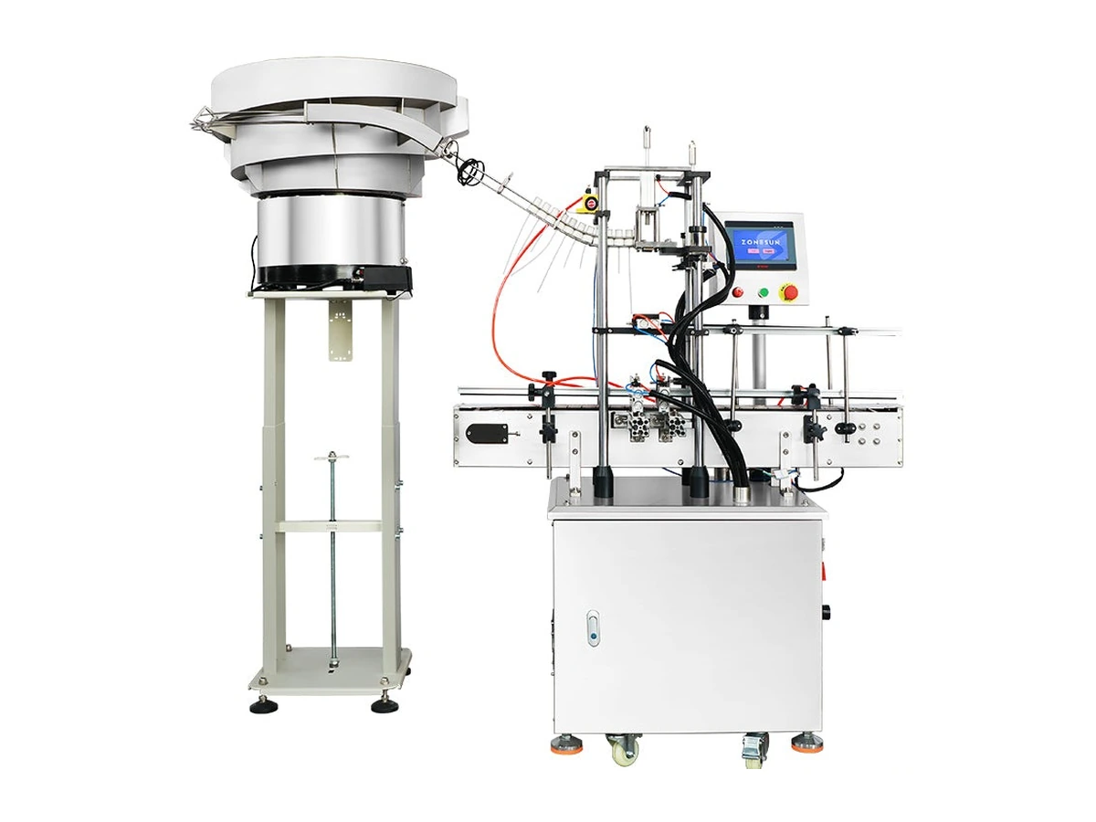
Orientation rule
The feeder specification should describe the accepted closure pose and the evidence that the dip tube remains suitable for insertion.
Identify the physical feature used to distinguish the required rotational direction and confirm that it is consistent across production components.
Define acceptable curvature, surface condition and tube-end presentation at the hand-off point.
State whether a closure is rejected, recirculated or stopped, and how repeated faults are detected.
Define low-level, full-buffer, capper-stop and restart behaviour so feeding does not continue uncontrolled.
Useful features are those that are mechanically repeatable and available on every approved closure, such as a body profile, nozzle position or moulded geometry. Colour, labels or temporary deformation should not be assumed to provide a reliable mechanical reference unless the system is specifically designed and tested for them.
The feeder should have an agreed path for incorrect presentations. Depending on the design, the closure may be returned for recirculation, diverted, or cause a controlled stop. The trial should confirm that this response does not damage the closure, overload the track or allow an incorrect cap to reach placement.
The buffer should provide enough correctly presented closures for normal demand while stopping or slowing before overfilling the track. Signals should also prevent uncontrolled feeding when the capper is blocked, stopped or unable to accept closures. The required buffer is a line-state decision, not only a bowl-capacity decision.
It may be possible when the approved closures share compatible geometry and the feeder has suitable change parts or settings. Significant differences in trigger body, nozzle direction, dip-tube length or stiffness can require different tooling or a separate feeding route. Confirm the complete format set with physical samples.
Compare the trigger spray cap feeder, the feeding-machine guide and the closure orientation page.