Stop the source of the tangle
Use the defined stop and safe-access procedure. Do not push more closures into a blocked path.

Feeder fault diagnosis
A direct engineering guide to trigger-head interlocking, dip-tube damage, recirculation, track blockage and demand control in automatic cap feeding.
Direct answer
Trigger closures can tangle or jam because flexible dip tubes overlap, trigger heads hook together, too many closures are loaded, the recirculation route bends tubes, mixed or damaged parts enter the feeder, track clearances are wrong, static or debris changes movement, or the downstream capper does not consume closures consistently. Diagnose the bulk-loading, orientation, transfer and demand sequence before increasing feeder speed.
A feeder trial must use production closures with their normal dip tubes and bulk-packaging condition. Tube-free samples or carefully hand-separated parts do not represent the entanglement and recirculation risk of normal operation.
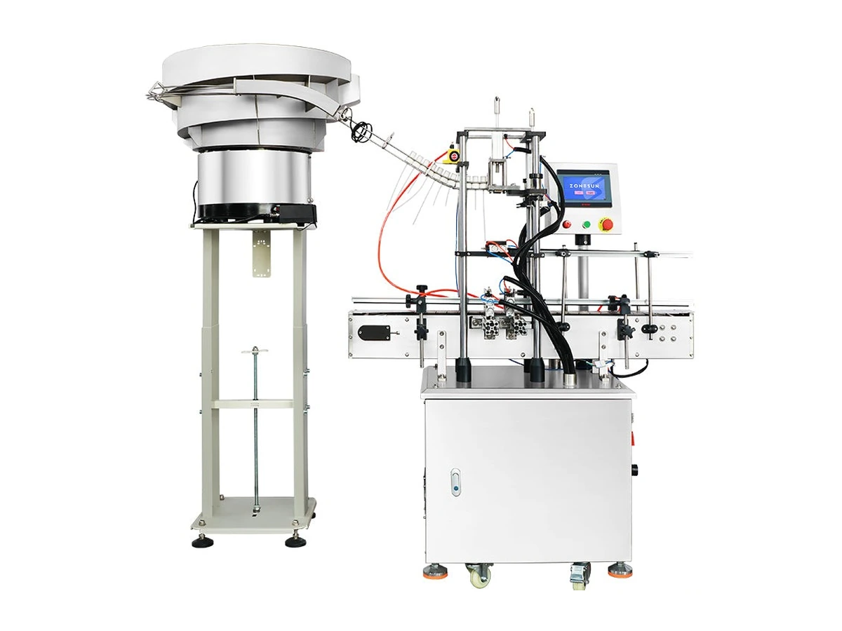
Fault isolation
| Observed problem | Possible mechanism | Evidence to capture |
|---|---|---|
| Closures lock together in bulk | Trigger levers, nozzles or tubes hook together; load depth or agitation increases interlocking. | Closure geometry, tube length/flexibility, bulk depth, packaging condition and video of the first tangle. |
| Tubes bend or curl during recirculation | Repeated falls, tight return path, compression or contact with tooling changes tube shape. | Number of recirculation passes, retained new/recirculated samples and tube-condition criteria. |
| Correct head orientation but tube misbehaviour | The trigger body is controlled while the free tube swings, catches or enters the next closure. | Tube path, guide clearance, transfer speed and downstream hand-off. |
| Track repeatedly blocks | Mixed format, damaged moulding, wrong clearance, burr, debris, static or inconsistent centre of gravity. | Rejected part, track position, lot, setting and clean/inspection condition. |
| Feeder empties or overfills the track | Demand signal, buffer control or downstream stop response is unstable. | High/low level states, capper demand, starved/blocked state and event timing. |
Recovery
Use the defined stop and safe-access procedure. Do not push more closures into a blocked path.
Keep tangled, damaged and apparently acceptable closures with lot and event identity so the cause can be reviewed.
Inspect hopper, bowl, return route, orientation tooling, track, escapement and transfer point rather than only the visible blockage.
Check buffer level, capper demand, downstream stop response and the rule for recirculating or rejecting suspect closures.
Confirm orientation, tube condition, placement, thread engagement, cap height and finished-pack quality before normal acceptance resumes.
Related questions
No. It may reduce agitation, but it cannot correct unsuitable bulk geometry, excessive load depth, a damaging recirculation route, mixed formats, wrong tooling or unstable downstream demand.
Use the site’s approved component-disposition rule. Tubes, trigger bodies, seals or threads may be damaged without an obvious external mark. Inspect and segregate suspect parts rather than automatically returning them to bulk.
Bulk packing can create tube curvature, compression, interlocking and debris that hand-separated samples do not show. The trial should reproduce how closures arrive, are loaded and are replenished.
Possibly, but each head geometry, centre of gravity, dip tube and required final orientation must be proved. Tooling, recipes or change parts may be needed, and the most difficult format can govern the feeder route.
Manual placement may be more practical for low volumes, frequent format changes, unstable bulk behaviour or closures that cannot be fed reliably without disproportionate complexity. Compare labour, ergonomics, quality and output using representative work.
Send production closures in their normal bulk condition, plus tube dimensions, required orientation, target demand and details of the downstream capper.