Best used when
The bottle, cap and output target fit this machine route better than a generic capper or a fully bespoke line.

Automatic trigger-sprayer capping system for cleaning, care and chemical bottles requiring stable cap presentation and repeatable closure control.
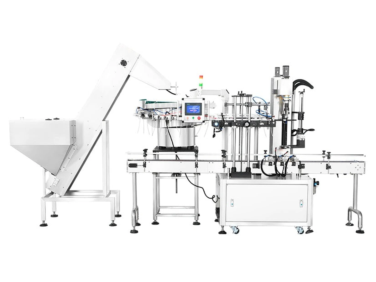
Machine intent
This page is focused on automatic trigger sprayer capping for bottles using trigger spray closures with dip tubes. It is the best route when you need controlled cap presentation, bottle transfer and repeatable tightening rather than simple manual cap placement.
The bottle, cap and output target fit this machine route better than a generic capper or a fully bespoke line.
Send cap samples, bottle samples, closure dimensions, tube length where relevant and the target output so tooling and configuration can be checked.
Use the quote form or call Lancing to compare this machine against the other trigger capping and spray bottle capping options.
Machine overview
Automatic trigger-sprayer capping system for cleaning, care and chemical bottles requiring stable cap presentation and repeatable closure control.
Applications
This machine is normally considered where the closure family, output target and container format need a practical balance between automation, operator involvement and changeover flexibility.
Specifications
Final machine configuration, guarding, conveyor height and options should be confirmed against your actual bottle and cap samples.
| Capacity | 1200 BPH |
|---|---|
| Voltage | 110V/220V |
| Applicable cap | Trigger sprayer, customisable |
| Applicable bottle size | Customisable |
| Conveyor | 2400 × 114mm, VFD |
| Size (L×W×H) | 3264 × 1345 × 2850mm |
Before quotation
Better samples and project data reduce guesswork and make the first proposal more accurate.
Send photos, drawings or physical samples showing cap diameter, closure style, thread and dip-tube length where relevant.
Confirm target bottles per minute or bottles per hour, plus whether the line is manually loaded or fully automatic.
Confirm available footprint, conveyor height, upstream filling equipment and downstream labelling or packing stages.
Machine application and acceptance
The published specification is a reference configuration. Final output, tooling and line layout should be confirmed using the actual bottle, trigger and dip tube, including normal manufacturing variation.
Closures are presented to the capping process, the tube is guided into a supported bottle, the cap is seated and the closure is tightened before discharge.
Cleaning, care and chemical spray bottles where a dedicated automatic route is justified by output and labour requirements.
Bottle guides, closure tooling, tube-entry method, conveyor height, guarding, controls and connections to adjacent machinery.
Actual sustained output, closure feed method, bottle stability, tube variation, changeover range and reject strategy.
| Sample set | All bottle and trigger combinations, including worst-case tube length, curvature and bottle stability. |
|---|---|
| Reference output | Validate the stated 1,200 BPH reference under the agreed sample, replenishment and quality conditions. |
| Quality checks | Cap seated correctly, thread engaged, tube inside bottle, acceptable torque/cap height and no visible damage. |
| Run evidence | Record accepted output, rejects, feeder/placement interruptions and any sample-specific adjustments. |
| Changeover | Demonstrate tooling and recipe changes for the agreed format range. |
| Handover | Manuals, drawings, recommended spares, operator training and maintenance checks. |
Related machines
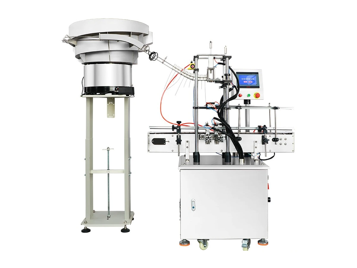
Vibratory bowl trigger-spray cap feeding and placement equipment for bottles with soft dip tubes and awkward trigger closure geometry.
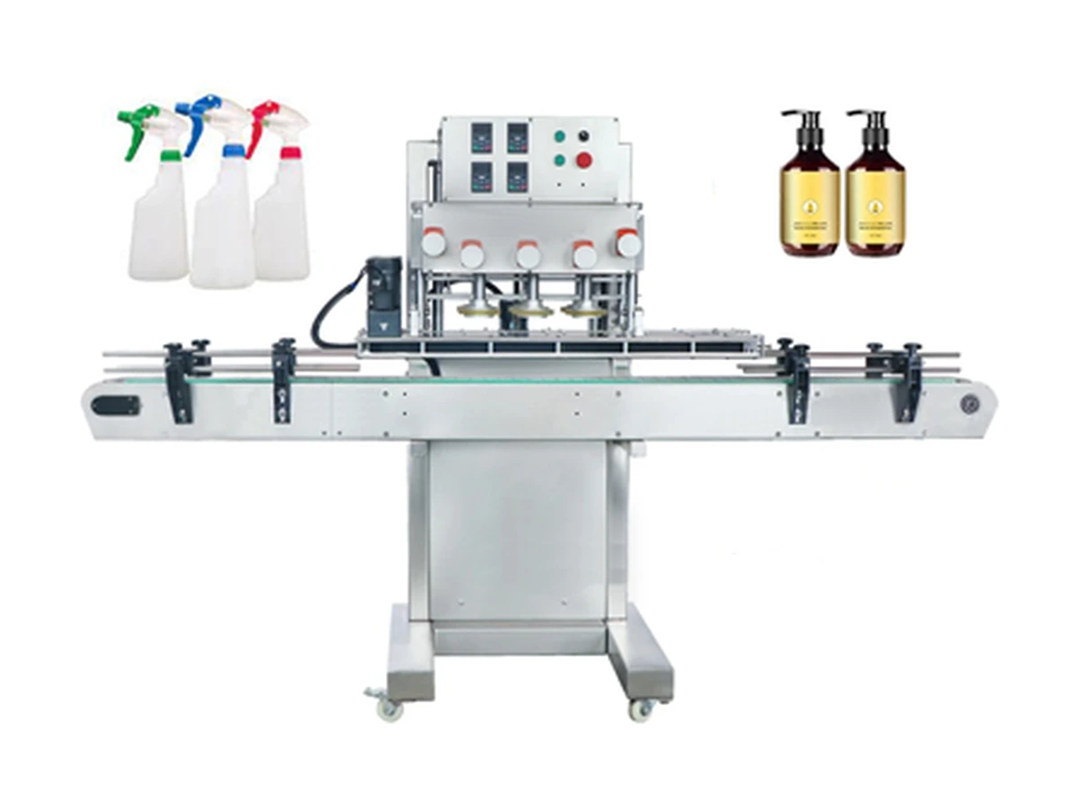
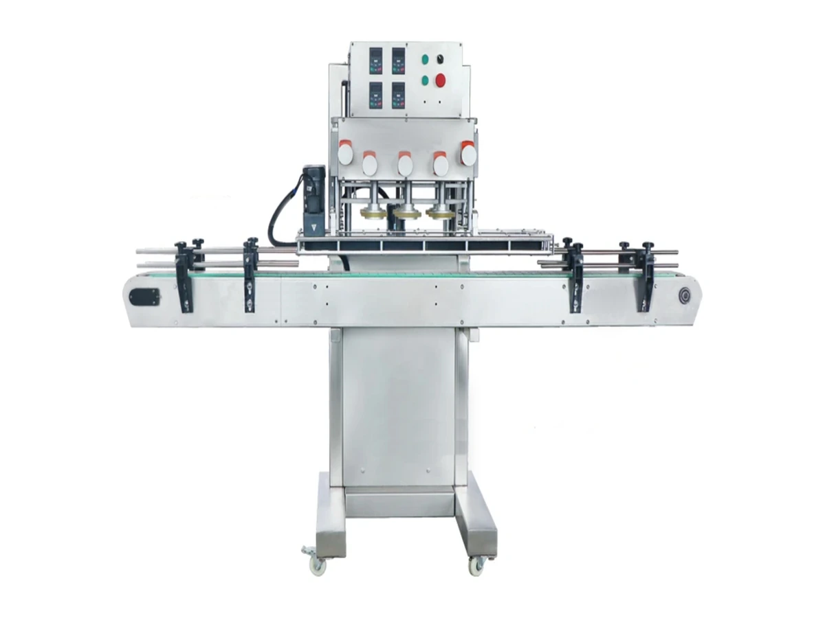
High-speed inline belt/spindle screw capper for round plastic bottles, with guided side-belt transport and cap feeding options.
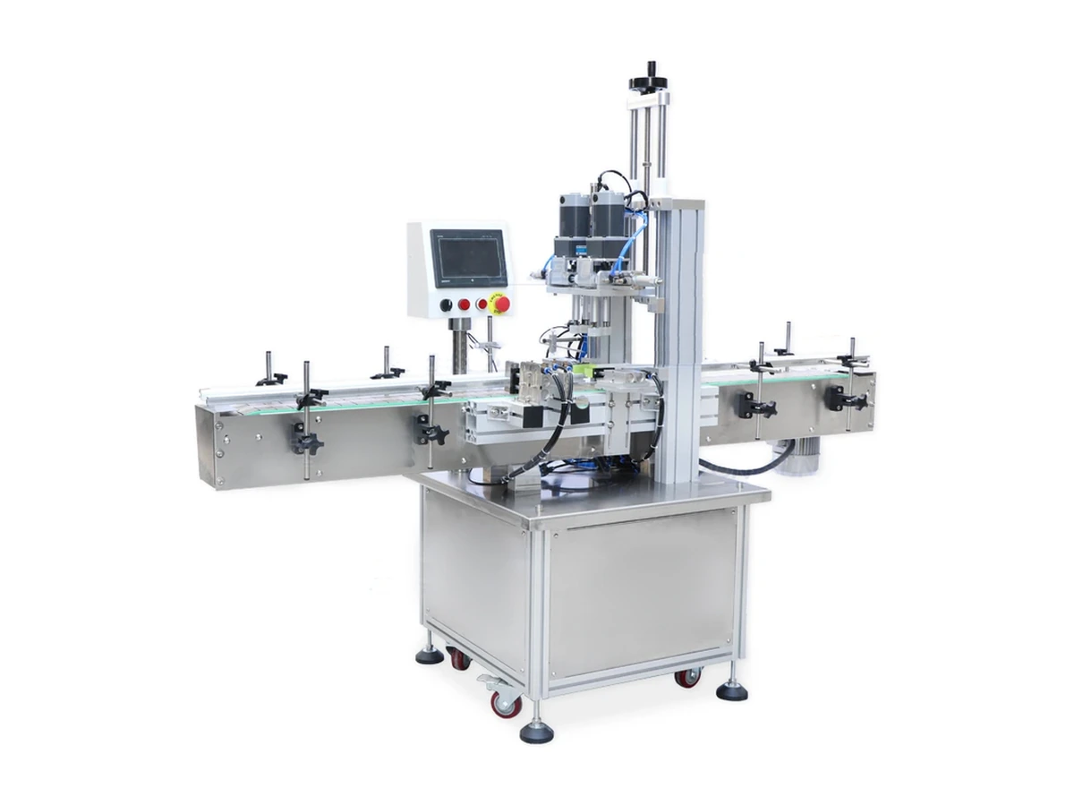
Pneumatic inline screw capping machine for spray, pump and screw-cap bottles with adjustable fixtures and repeatable torque control.
Space-saving screw capper for smaller production areas, laboratories and compact lines running sprays or standard screw caps.
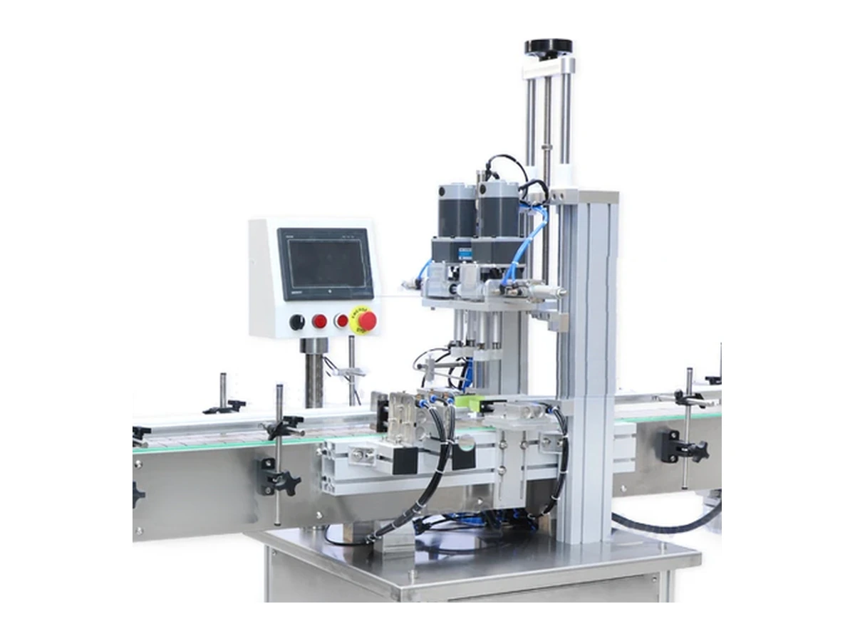
Desktop semi-automatic screw capper with automatic bottle clamping, manual/automatic cycling and stable torque control for smaller batches.
Send bottle, cap, closure sample and output target to Lancing UK.
Automatic line acceptance
The 1,200 BPH figure is a reference capacity for the listed configuration. Final accepted output should be stated with the actual bottle, trigger, dip tube, closure-feed arrangement, operator duties and quality criteria.
| Stage | Configuration question | Evidence to record |
|---|---|---|
| Closure supply and buffer | How are triggers loaded, orientated and buffered before demand from the placement station? | Replenishment events, starvation, misorientation, recirculation and tube condition. |
| Transfer and tube entry | How is the trigger held and how is the tube guided through the bottle neck? | Missed entries, trapped tubes, kinks, cuts and contact with guides or bottle shoulders. |
| Placement and pre-threading | How is the closure centred, seated and started on the thread before final tightening? | Cross-threading, cocked caps, cap-height result and bottle movement. |
| Final tightening | What is the torque application method and how is the bottle stabilised? | Torque results using the agreed gauge and timing, plus cosmetic condition of the cap and bottle. |
| Inspection and discharge | Which faults cause a stop or reject, and how are accepted packs counted? | Accepted output, rejected packs, stop causes and the disposition of affected bottles. |
| Recovery and changeover | How are jams cleared, the transfer path checked and another SKU set up? | Restart sequence, first-off approval, tooling/settings changed and time to a stable accepted run. |
Choose fixed bottle and closure reference points and measure after the same settling period. A high cap can indicate incomplete placement, poor thread start or unsuitable tightening setup.
Use a calibrated method appropriate to the closure. Record the instrument, procedure, sample timing and required window rather than publishing an unsupported universal value.
Agree ready, run, fault and stop behaviour with filling, conveyors and labelling. A capper should not continue to consume buffer when downstream flow is blocked.
Automatic capper questions
The final rate must be validated with the agreed bottle, trigger, tube, feed method, operator duties, replenishment pattern, run duration and accepted-quality criteria.
Orientation can be included where the feeder, transfer and final pack requirement are defined. The exact method depends on the trigger geometry and must be proved with samples.
The feed and placement route should keep the tube clear, guide it toward the neck and avoid kinking or trapping. Worst-case production-age tubes should be included in trials.
A controlled thread-start stage may be required before final torque. The selected sequence depends on closure design, bottle neck, placement accuracy and the machine configuration.
Test the least stable bottle at production fill weight through guides, placement and tightening. Guide or side-support requirements should be agreed from that result.
Demonstrate tooling, guide, height, recipe and feeder changes, followed by first-off checks for tube entry, thread engagement, cap height, torque and orientation.
Demonstration evidence
The supplied demonstration is useful evidence of the reference machine’s indexed bottle handling and vertical capping-head cycle. It is not a substitute for a production trial with the actual trigger, dip tube, filled bottle, feeder route and agreed finished-pack checks.
| Video interval | Visible in the supplied footage | What still requires separate confirmation |
|---|---|---|
| 0–5 seconds | White bottles are located around an indexed rotary transfer, with the central vertical head above the bottle path and trigger-spray closures visible on some bottles. | The bulk closure-loading method, trigger orientation rule, tube condition before placement and the controls that release a closure to the station. |
| 5–12 seconds | The capping head moves vertically while bottles remain held in the indexed transfer positions. | The force or torque method, cap-height acceptance window, thread-start quality and the result on the buyer’s bottle and trigger combination. |
| 12–20 seconds | The rotary transfer advances bottles through repeated head cycles, showing the relationship between bottle indexing and the working station. | Sustained accepted output, normal feeder replenishment, reject handling, line blockage and interaction with upstream or downstream machinery. |
| 20–25 seconds | The repeated sequence continues with trigger-spray bottles visible around the transfer and at the edge of the working area. | Changeover time, jam detection, safe recovery, first-off approval and performance across every proposed bottle, trigger and dip-tube format. |
The footage shows indexed bottle control and repeated vertical head movement. It can support an early mechanical discussion about bottle location and working sequence.
Finished-pack quality needs measured checks on production samples. Record tube entry, thread engagement, cap height, torque method, trigger direction and visible damage using agreed references.
A normal running video does not prove response to a misoriented closure, trapped tube or interrupted cycle. Those conditions need a controlled trial and an agreed safe recovery sequence.
State the bottle and trigger format, dip-tube condition, closure-feed method, operator replenishment work, run duration and accepted-quality criteria. Count accepted bottles and record stops, rejects, feeder starvation, placement faults and recovery events. This keeps the published reference capacity in context and prevents a raw cycle figure being mistaken for a guaranteed line result.
Production evidence
The published 1,200 BPH value is a reference for the listed machine configuration. The final project record should state the actual bottle, trigger, dip tube, cap-feed arrangement, operator work, run duration, quality checks and treatment of stops.
| Record field | What to capture for the project |
|---|---|
| Reference format | Bottle and closure identity, filled weight, neck finish, tube length/condition, nozzle direction and tooling/settings revision. |
| Closure supply | Loading method, normal replenishment, orientation rule, usable buffer and any recirculation or tube-damage limit. |
| Run definition | Start/finish time, planned operator duties, line states included and whether upstream/downstream machines were connected. |
| Finished-pack quality | Tube entry, thread engagement, cap height, torque or approved closure method, cosmetic condition and orientation. |
| Performance record | Accepted packs, rejects by reason, starved/blocked time, faults, interventions and recovery actions. |
| Release | First-off approval, retained samples, open actions and the person accepting the result. |
Use the trigger capper FAT and SAT checklist, quality inspection guide and controls and data guide to build the record.
Production questions
Use these checks to turn the machine reference into an application-specific operating and acceptance brief.
The agreed sequence should prevent a closure being placed or released into an empty station, preserve the correct machine state and avoid uncontrolled closure accumulation. The trial should include bottle absence, spacing gaps and restart so the response is verified rather than inferred from normal running.
The machine and quality plan should define whether the condition is detected automatically, stopped for investigation or found by downstream inspection. In every case, affected bottles must be identified and held, and the recovery check should cover tube entry, thread engagement, cap height, torque or approved alternative, and appearance.
State the exact bottle, closure, dip tube, feeder arrangement, operator duties, run duration, quality checks, planned stops and accepted-output definition. The published 1,200 bottles-per-hour value on this page is a reference; the project result must be demonstrated with the approved production samples and conditions.
The change can involve bottle guides, side belts or clamps, cap handling parts, placement tooling, head height, tightening contact, recipes and inspection references. The exact list depends on the approved format family, so the quotation and trial should identify reusable settings separately from physical change parts.
Run evidence
The reference machine data on this page is useful only when the production bottle, trigger closure, dip tube, feeder behaviour and inspection method are defined. A trial record should make it possible to repeat the result and explain every interruption or rejected pack.
A component-lot change should be included when normal production is likely to use more than one bottle or closure lot, or where previous variation has affected feeding, thread engagement or tube entry. Record the lot identity and compare the same quality checks before changing machine settings.
Accepted output is the number of packs that pass the agreed finished-pack checks during the defined run period. It should exclude rejected packs, setup bottles and packs held after a fault or adjustment. The record should also show starved, blocked and planned-stop time so the result is not confused with mechanical cycle rate.
Retain approved first-off and representative run samples for each agreed format, together with any useful defect examples. Label them with bottle and closure identity, date, machine settings revision and the inspection result. Retained samples help distinguish later component drift from a machine or setup change.
A production run log connects accepted packs with the conditions that produced them. It records component lots, settings, line states, replenishment, rejects, faults and recovery. Without that context, a headline output number cannot show whether the feeder, capper, conveyor or components limited the line.
Use the trigger capping sample trial matrix before formal acceptance, then keep the production run log with the quality and fault record.