Best used when
The bottle, cap and output target fit this machine route better than a generic capper or a fully bespoke line.

Vibratory bowl trigger-spray cap feeding and placement equipment for bottles with soft dip tubes and awkward trigger closure geometry.
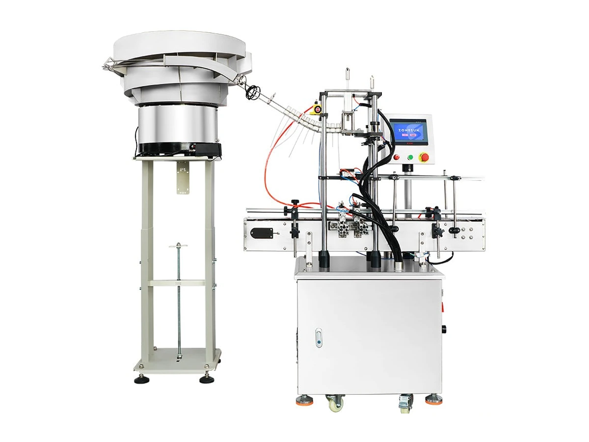
Machine intent
This page is focused on trigger spray cap feeding equipment. It is relevant when the trigger closure shape or dip tube makes manual placement slow, inconsistent or unsuitable for the target line speed.
The bottle, cap and output target fit this machine route better than a generic capper or a fully bespoke line.
Send cap samples, bottle samples, closure dimensions, tube length where relevant and the target output so tooling and configuration can be checked.
Use the quote form or call Lancing to compare this machine against the other trigger capping and spray bottle capping options.
Machine overview
Vibratory bowl trigger-spray cap feeding and placement equipment for bottles with soft dip tubes and awkward trigger closure geometry.
Applications
This machine is normally considered where the closure family, output target and container format need a practical balance between automation, operator involvement and changeover flexibility.
Specifications
Final machine configuration, guarding, conveyor height and options should be confirmed against your actual bottle and cap samples.
| Machine model | LU-XG446S |
|---|---|
| Voltage | 110/220V 50–60Hz 250W |
| Suitable cap size | Approx. Ø15–35mm |
| Suitable bottle height | Approx. 10–280mm |
| Working capacity | 20–25 BPM |
| Package size | 1420 × 680 × 1740mm main machine + 940 × 930 × 820mm bowl sorter |
| Package weight | Approx. 210kg main machine + 153kg bowl sorter |
Before quotation
Better samples and project data reduce guesswork and make the first proposal more accurate.
Send photos, drawings or physical samples showing cap diameter, closure style, thread and dip-tube length where relevant.
Confirm target bottles per minute or bottles per hour, plus whether the line is manually loaded or fully automatic.
Confirm available footprint, conveyor height, upstream filling equipment and downstream labelling or packing stages.
Feeder validation
The reference feeder specification gives a starting point, but reliable operation depends on the exact trigger geometry, tube behaviour and required presentation angle. Sample trials should be part of final configuration.
Confirm that closures separate without nesting, bridging or excessive tube tangling in the bowl and loading method.
Define the trigger/nozzle orientation required at discharge and how incorrect parts are rejected or recirculated.
Check track pitch, buffer, hand-off and tube clearance through the full route to the placement station.
List all cap sizes and tube variants, then identify tooling, settings and verification needed for each changeover.
| Reference range | Confirm each closure against the stated approximate 15–35 mm cap range rather than relying on diameter alone. |
|---|---|
| Reference capacity | Validate the stated 20–25 BPM working capacity with actual closures and the proposed transfer route. |
| Orientation quality | Measure correctly presented caps, recirculation, false accepts and jams during a representative run. |
| Tube damage | Inspect for kinks, stretching, flattening, cuts or entanglement after circulation. |
| Buffer/recovery | Check track capacity and restart after normal replenishment or short stops. |
| Changeover | Demonstrate tooling, settings, cleaning and first-off checks for each agreed closure. |
Related machines
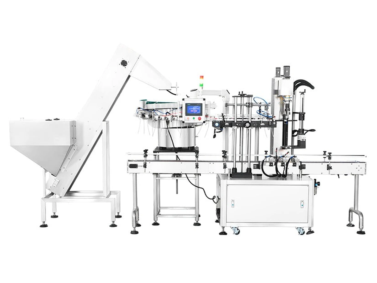
Automatic trigger-sprayer capping system for cleaning, care and chemical bottles requiring stable cap presentation and repeatable closure control.
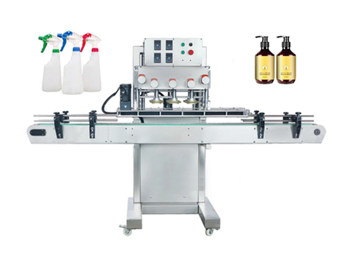
High-speed inline belt/spindle screw capper for round plastic bottles, with guided side-belt transport and cap feeding options.
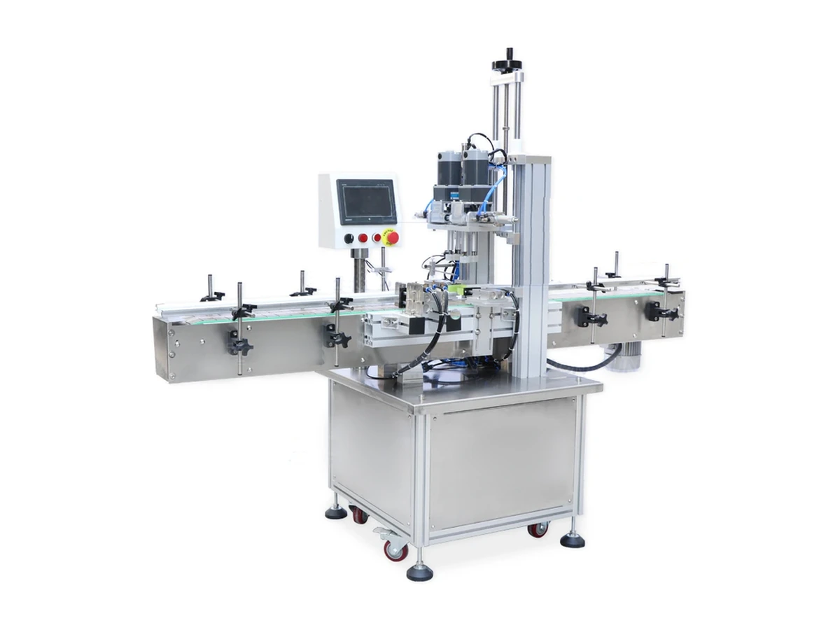
Pneumatic inline screw capping machine for spray, pump and screw-cap bottles with adjustable fixtures and repeatable torque control.
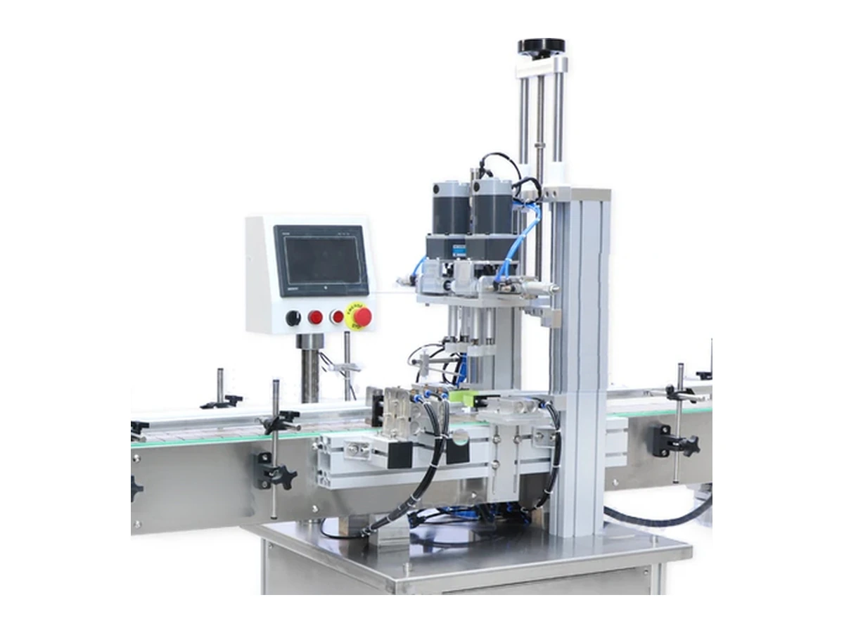
Space-saving screw capper for smaller production areas, laboratories and compact lines running sprays or standard screw caps.
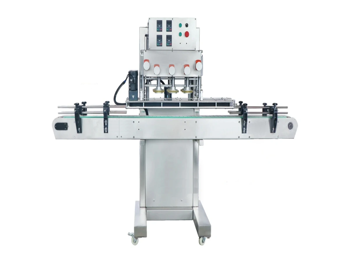
Desktop semi-automatic screw capper with automatic bottle clamping, manual/automatic cycling and stable torque control for smaller batches.
Send bottle, cap, closure sample and output target to Lancing UK.
Feeder trial protocol
The stated 20–25 BPM working capacity and approximate Ø15–35 mm cap range are reference values. Trigger shape, centre of gravity, tube length, tube curl, required orientation and downstream hand-off determine whether that rate is sustainable.
| Trial area | What to observe | Acceptance evidence |
|---|---|---|
| Bulk loading | Nesting, bridging, tube tangling and damage during normal operator replenishment. | Representative loading quantity and replenishment method recorded. |
| Bowl separation | Whether closures separate cleanly without excessive recirculation or tube abrasion. | Correctly separated parts, rejects, recirculation and damaged tubes counted. |
| Orientation | Trigger/nozzle direction at the discharge point and false accepts through the tooling. | Defined orientation rule and measured correct-presentation rate. |
| Track and buffer | Cap pitch, tube clearance, available buffer and response to capper demand. | Buffer supports normal short stops and replenishment without starving the capper. |
| Hand-off | Gripper or transfer contact, tube path and placement position at the bottle. | No unacceptable marking, dropped parts, trapped tubes or missed placement. |
| Jam and restart | Fault detection, safe access, removal of affected closures and line restart. | Transfer path inspected and first correctly presented parts approved after restart. |
| Changeover | Tooling, track, sensor and recipe adjustments for every trigger family. | Parts/settings list and first-off checks completed for each agreed format. |
A useful buffer absorbs normal variation between feeder presentation and capper demand. It also needs low-level detection, demand control and defined behaviour during downstream stops so closures are not continually circulated or pushed into a blocked hand-off.
Feeder questions
No. The approximate Ø15–35 mm reference is only a starting point. Trigger shape, tube, centre of gravity and required orientation determine the tooling.
The rate should be validated with the production closure, loading method, orientation rule, tube-quality criteria, buffer and downstream transfer.
They can be kinked, stretched, flattened or tangled if the tooling and circulation route are unsuitable. Trials should inspect tubes after recirculation as well as after capping.
Incorrect closures may be rejected or recirculated before hand-off. The method depends on the closure geometry and the final trigger direction required.
Feeder demand and buffer control should prevent uncontrolled accumulation. Restart should verify the hand-off path and the first correctly presented closure.
Possibly, but each closure may require tooling, track, sensor or setting changes. The complete format list must be trialled and documented.
Feeder demand and recovery
The 20–25 BPM figure is a reference working capacity for the LU-XG446S. A useful trial should show that correctly orientated closures remain available at the capper under normal loading, short stops and controlled restart without unacceptable tube damage.
| Feeder condition | What to test | What to record |
|---|---|---|
| Normal replenishment | Approved loading quantity and method while the feeder and downstream machine operate. | Operator intervention, nesting, tube tangling, buffer level and any output interruption. |
| Short downstream stop | Response when the capper cannot consume closures temporarily. | Demand signal, recirculation, track pressure, tube condition and controlled restart. |
| Low closure supply | Detection and response before the placement station is starved. | Warning/stop point, remaining usable buffer and recovery after replenishment. |
| Misorientation or jam | Detection, safe clearance, inspection of the transfer path and first correct hand-offs. | Affected closures, cause, recovery sequence and first-off approval. |
| Format change | Tooling, track, sensor, bowl and recipe adjustments for each trigger family. | Parts/settings record, orientation result and tube-quality check. |
Define the line-state signals in the controls and sensor guide, record pack checks with the quality inspection guide and include feeder recovery in the FAT and SAT plan.
Feeder questions
Automatic orientation has to protect the component while supplying the capper in the correct state.
The asymmetric body, nozzle, shipping clip and attached dip tube can create several stable but incorrect positions. Long, soft or naturally curved tubes may trail, overlap or catch. Suitability therefore depends on the complete physical closure, not only the threaded skirt or nominal diameter.
An incorrectly presented closure may pass through the bowl more than once. The return path should avoid sharp bends, trapping, abrasion and uncontrolled drops that can change tube shape or damage the tube end. Repeated recirculation should be included in component-condition checks during the trial.
Level and line-state signals can be used to start, stop or regulate feeding so the track stays within its working buffer. The logic should account for capper stops, downstream blockage, low closure level and restart, preventing both starvation and excessive accumulation.
Manual loading may be more appropriate for short campaigns, frequent closure changes, low demand or components that are difficult to orient automatically. The decision should compare sustainable operator work, consistency, format flexibility, space and the evidence available from sample trials rather than automation level alone.
Read how trigger closures are oriented, the feeding-machine guide and the buffer and control guide.
Component control
A trigger feeder reacts to the complete closure: actuator shape, moulding features, thread, dip-tube attachment, tube length, curvature and surface condition. Incoming checks make it easier to tell whether a new fault comes from the feeder setup or from the components supplied to it.
| Closure feature | Why the feeder is affected | Practical check |
|---|---|---|
| Trigger-body geometry | Ribs, levers, nozzle position and asymmetry determine how the part nests, separates and reaches the orientation tooling. | Compare the production lot with the approved sample and drawing revision where available. |
| Dip-tube attachment and length | A loose, curled, overlong or damaged tube may tangle, drag or enter the track differently. | Record the agreed length reference, tube end condition and any curvature before loading the bowl. |
| Moulding flash or distortion | Raised edges or distorted parts can catch on tooling or produce false orientation. | Inspect known contact points and retain defect examples for supplier review. |
| Surface condition | Oil, dust, static or product contamination may change sliding and separation behaviour. | Compare clean production-intent components under the agreed environmental condition. |
| Bulk packing condition | Compression, heat or transport can set dip tubes into curves or create nested bundles. | Trial closures taken from normal production packaging, not only hand-selected loose samples. |
No. First compare the new closure lot with the approved reference and record any change in trigger geometry, tube condition or surface behaviour. A setting change should be controlled and documented only after the component difference and resulting feeder behaviour are understood.
Normal bulk packaging can affect dip-tube curvature, nesting and static. Hand-selected loose closures may feed more easily than the material operators will actually load. A representative feeder trial should include the normal pack condition and replenishment method.
Record the length using an agreed reference point on the closure and state whether the value is total or usable length. Also record tube outside diameter, end cut, material, curvature and attachment condition because equal nominal lengths can behave differently in a bowl or track.
Record the component lot, orientation rule, location of the false accept, feeder settings and photographs or video of the part entering and leaving the tooling. Retain the affected closure and compare it with an approved sample before changing guides or sensors.
See the incoming trigger-closure quality checks and the answer to how dip-tube length should be specified.
Fault diagnosis
When closures jam, identify whether the first loss of control occurs in bulk loading, recirculation, orientation, track transfer or downstream demand.
Greater agitation can increase head interlocking, tube overlap and recirculation damage. The correct setting is the lowest stable action that maintains controlled supply for the proven closure.
Keep representative tangled, damaged and apparently acceptable closures with the lot, load condition, feeder state and event time. They help distinguish tooling, component and demand causes.
Overfilling can increase pressure and recirculation, while poor low-level control can starve the capper. High/low states and downstream demand should be reviewed with the physical feed path.
Read why trigger closures tangle or jam in a cap feeder and use the OEE and downtime guide to code recurring feeder losses.