Conveyor integration
The capper must receive bottles at a pace that matches filling and labelling.

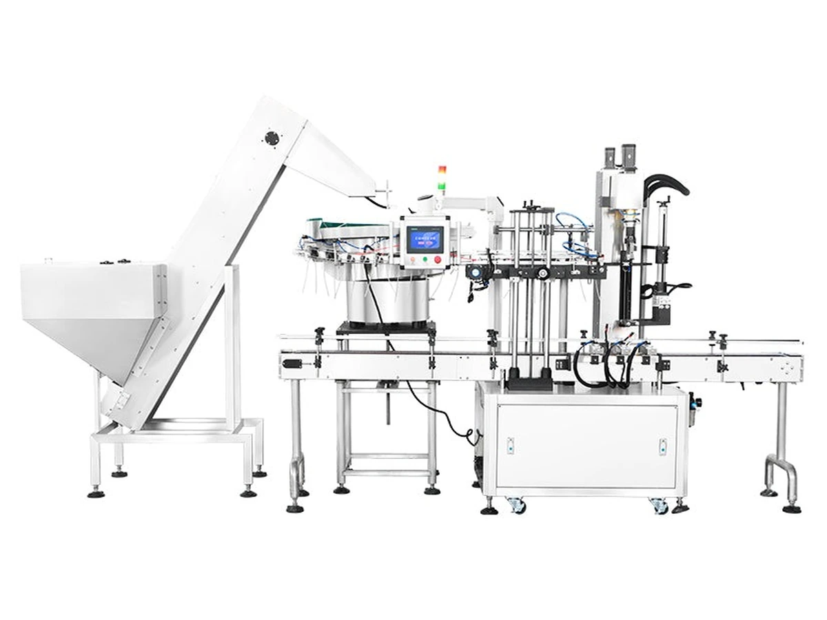
Inline trigger capping machine
An inline trigger capping machine is normally selected when bottles move through filling, capping, labelling and packing as part of a connected line. Conveyor control and bottle spacing are as important as the capping head itself.
Buyer guidance
This page is aimed at buyers comparing inline capping machinery for conveyor-fed production. The right machine route depends on the cap, bottle, dip tube, output target and the wider line rather than the machine name alone.
Specification priorities
These points help narrow the shortlist before samples are reviewed or a formal quotation is prepared.
The capper must receive bottles at a pace that matches filling and labelling.
Indexing, timing screws, side belts or stops may be required for consistent positioning.
Inline routes can be planned so filling, coding, labelling or case packing can be added later.
Related machinery
Use these machine routes to compare the practical equipment options before sending samples for review.
Automatic capping route for cleaning, home-care and chemical bottles with trigger sprayers.
View machine →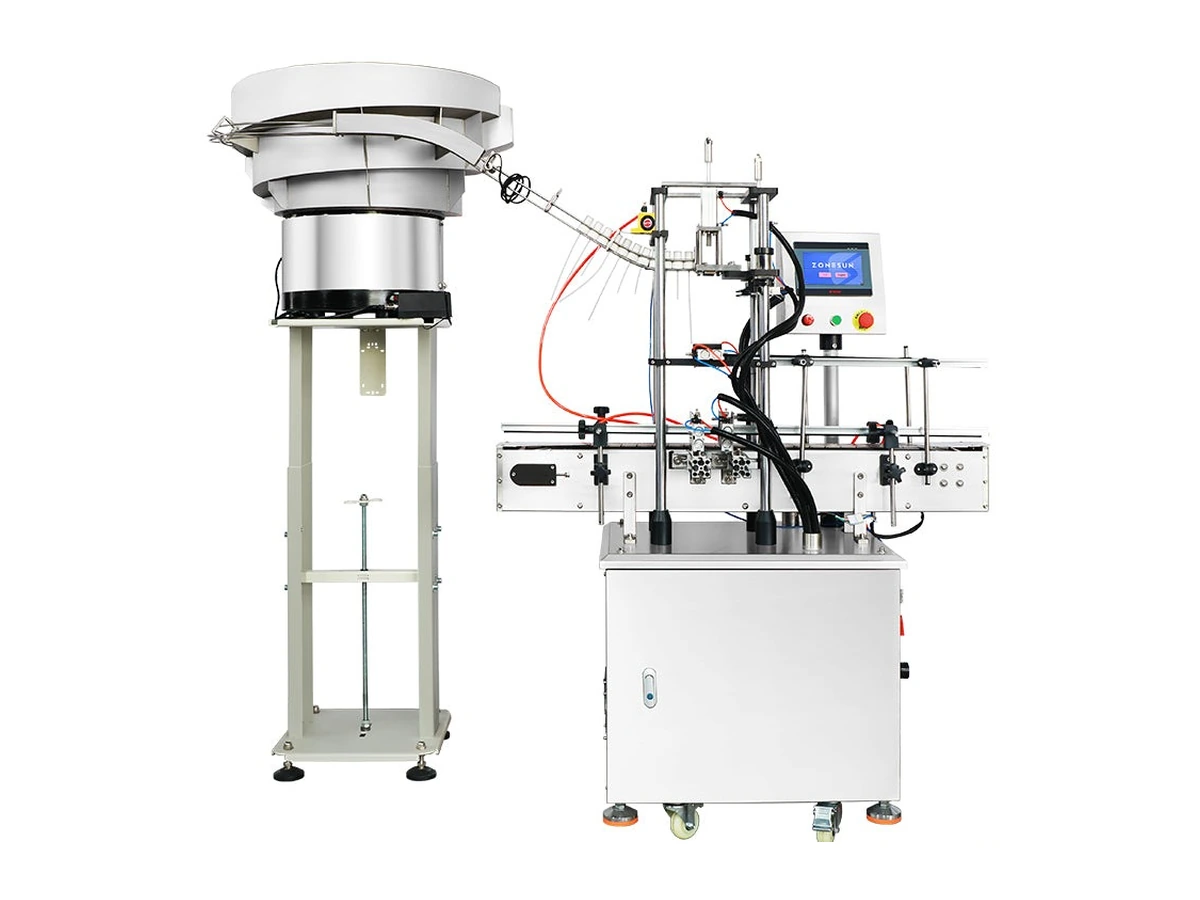
Feeding and orientation route for trigger sprayers with soft dip tubes.
View machine →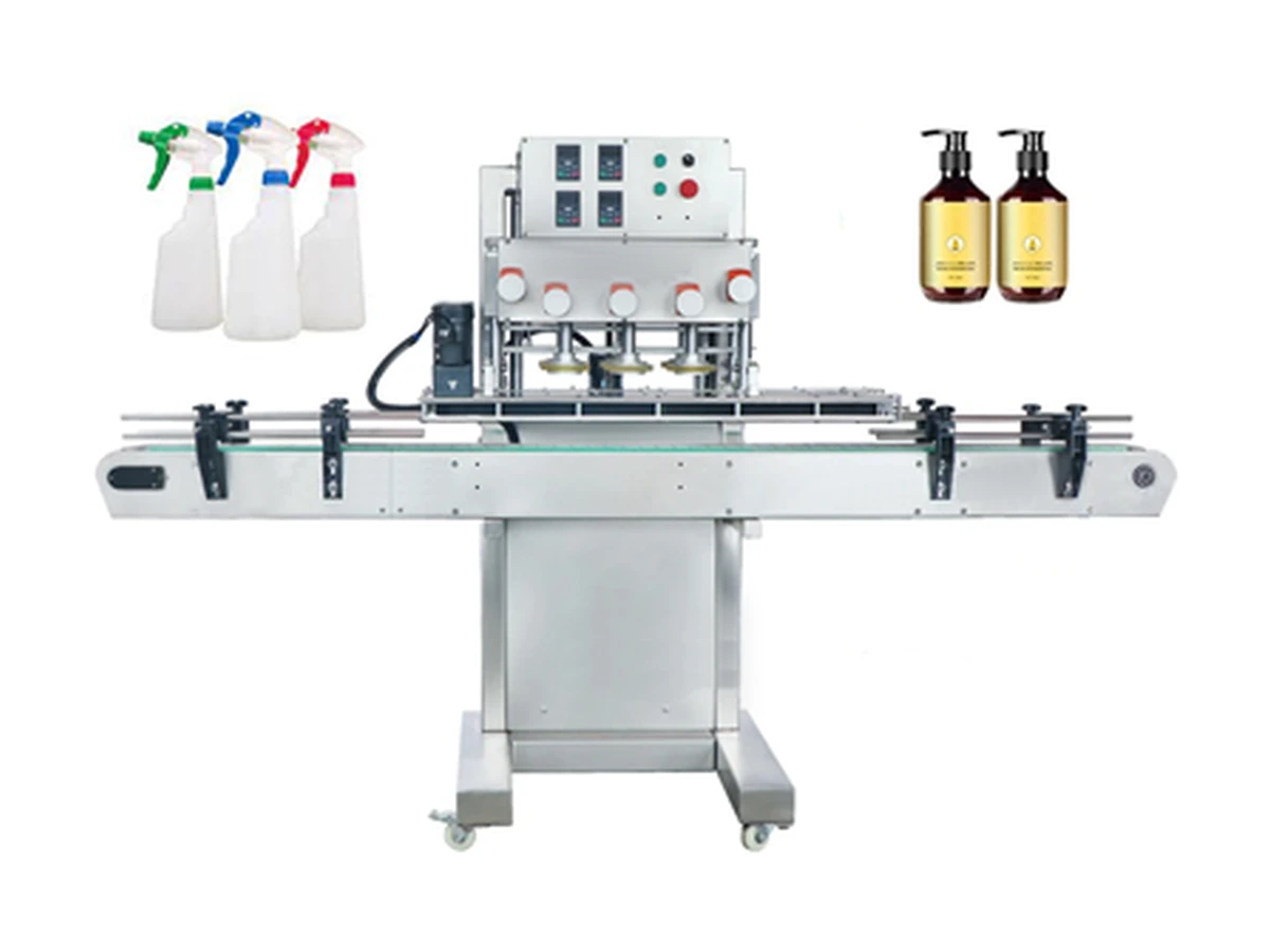
High-output inline belt and spindle capping route for compatible screw and spray closures.
View machine →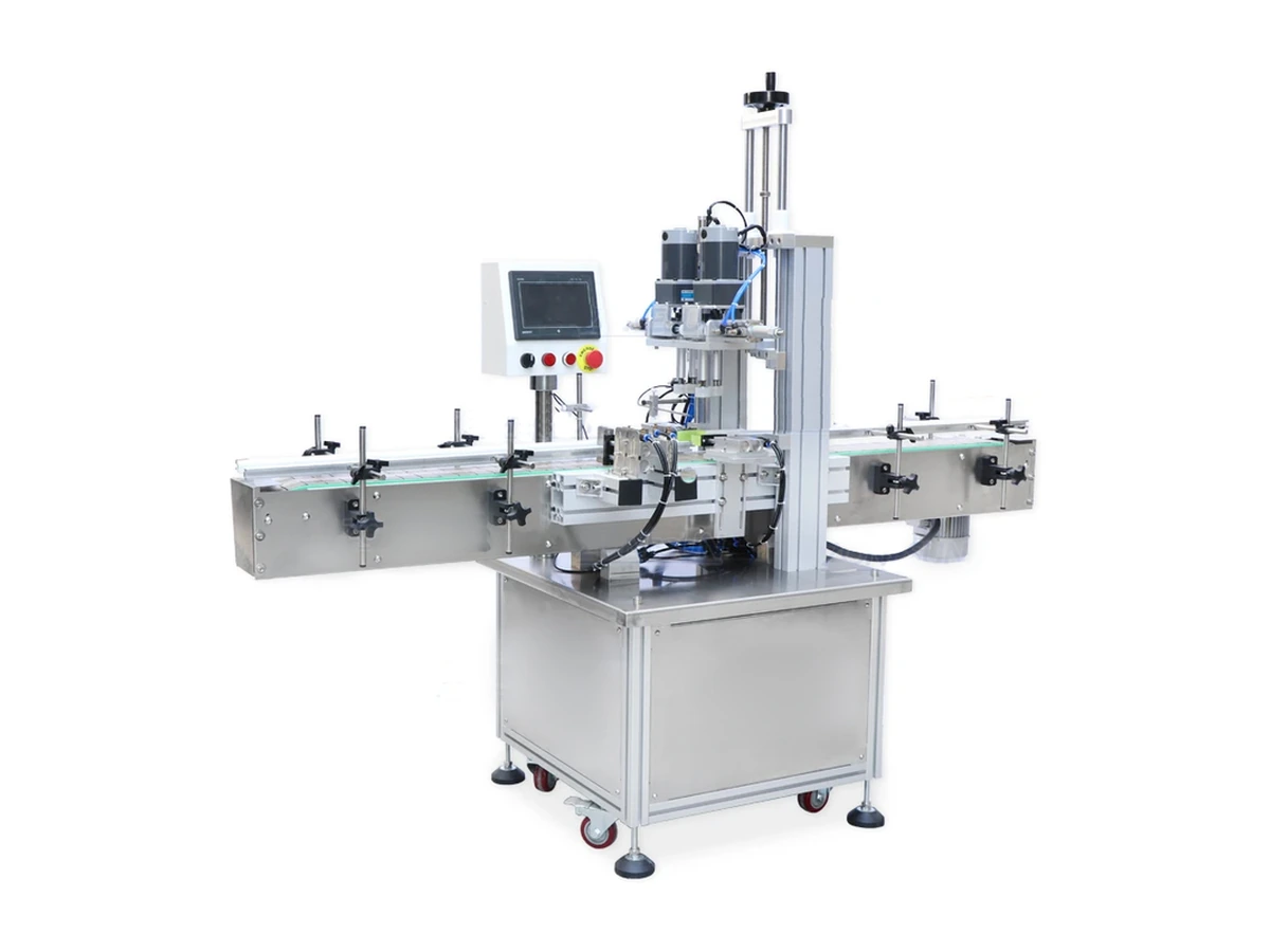
Automatic screw capping route for repeatable cap placement, torque and line integration.
View machine →Quick answers
It is a conveyorised capping system that caps bottles as part of a straight-line production flow.
Inline systems are often flexible and practical for varied formats. The best route depends on speed, footprint and changeover requirements.
Yes. Lancing can help review layout, conveyor interfaces, utilities and installation planning.
Send bottle samples, trigger caps, dip-tube length, product details and target output. Lancing can help compare semi-automatic, compact and automatic routes.
More routes
Line controls and interfaces
An inline trigger capping machine does not operate in isolation. A useful specification states what the capper expects from filling and conveying, what it reports to the wider line and how it behaves when bottles, closures or downstream capacity are unavailable.
Define the bottle formats, filled condition, neck presentation and spacing required at the infeed. The least stable filled bottle should remain upright through transfer, closure placement and tightening without relying on an operator to correct it.
State the required trigger direction, tube condition and presentation point. The capper should receive a closure in a known state, while feeder demand, low level, empty and fault conditions are clearly distinguished.
Define the checks needed before a bottle is released downstream: tube inside the container, closure seated, thread started, tightening completed and any agreed orientation or appearance requirement satisfied.
| Interface | Information to define | Evidence for acceptance |
|---|---|---|
| Upstream filler and transfer | Bottle format, filled weight, neck condition, conveyor height, pitch and the signal used when the capper cannot accept another bottle. | Representative bottles reach the infeed upright and correctly spaced during normal starts, stops and replenishment. |
| Trigger feeder and buffer | Demand, low-level, empty, blocked and fault states; the agreed orientation; tube-clearance route; and normal operator replenishment. | The buffer supports the agreed operating sequence without uncontrolled recirculation, damaged tubes or closure starvation during ordinary short interruptions. |
| Placement and pre-threading | Bottle-present and closure-present confirmation, tube-entry path, cap-height references and the method used to establish an initial thread start. | Agreed samples are placed consistently without trapped tubes, cocked closures or cross-threaded packs. |
| Tightening and bottle control | Head or spindle arrangement, side support, guide positions and the method used to verify finished-pack torque or cap height. | The least stable agreed bottle remains controlled and the finished closure meets the documented quality checks. |
| Downstream conveyor | Blocked or full state, accumulation allowance and the sequence used to stop upstream equipment without trapping bottles at the capping station. | A controlled stop and restart are demonstrated with affected bottles identified and checked before release. |
| Operator and fault recovery | Safe access, reset authority, affected-product disposition and the first-off checks required after a jam, guard opening or format adjustment. | The transfer path is inspected, the cause is recorded and the first accepted bottles are approved before normal running resumes. |
When bottles or correctly presented closures are unavailable, the line should wait in a defined state rather than cycling empty or consuming buffer without a pack to process.
When the next machine cannot accept bottles, the stop sequence should protect the capper, the buffer and any bottles already between placement, tightening and discharge.
A fault should identify the affected station and support a controlled inspection. Repeated resets without checking the transfer path can turn one damaged closure into a wider batch issue.